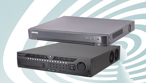
DVR - Digital video recorder | How a DVR works | CCTV Training Oman
A digital video recorder (DVR) is a consumer electronics device or application software that records video in a digital format to a disk drive(hard disk), USB flash drive, SD memory card, or other local or networked mass storage device. The term includes set-top boxes (STB) with direct to disk recording facility, portable media players (PMP) with recording, recorders (PMR) as camcorders that record onto Secure Digital memory cards and software for personal computers which enables video capture and playback to and from a hard disk drive. A television set with built-in digital video-recording facilities was introduced by LG in 2007 followed by other manufacturers.
Front panel
1. Status Indicators:
· POWER: the POWER indicator turns green when DVR is powered up.
· STATUS: the indicator lights when the compound key switches to numeric/letter input mode
· Tx/Rx: TX/RX indicator flickers green when the network connection is functioning normally
2. IR Receiver: operation by IR remote control
3. Compound Buttons :
· 1 MENU : (1) Enter numerical “1”; (2) Access the main menu interface
· 2ABC/F1: (1) Enter numerical “2”; (2) Enter letters “ABC”; (3) The F1 button when used in a list field will select all items on the list. In PTZ Control mode, it will turn on/off PTZ light.
· 3DEF/F2: (1) Enter numerical ‘”3”; (2) Enter letters “DEF”; (3) The F2 button is used to cycle through tab pages. It will also bring up the Channel & OSD Position settings.
· 4GHI/ESC: (1) Enter numerical “4”; (2) Enter letters “GHI”; (3) Exit and back to the previous menu.
· 5JKL/EDIT: (1) Enter numerical “5”; (2) Enter letters “JKL”; (3) Delete characters before cursor; (4) Select the check box and ON/OFF switch; (5) Start/stop record clipping in playback.
· 6MNO/PLAY: (1) Enter numerical “6”; (2) Enter letters “MNO”; (3) Playback, for direct access to playback interface.
· 7PQRS/REC: (1) Enter numerical “7”; (2) Enter letters “PQRS”; (3) Manual record, for direct access to manual record interface; manually enable/disable record.
· 8TUV/PTZ: (1) Enter numerical “8”; (2) Enter letters “TUV”; (3) Access PTZ control interface.
· 9WXYZ/PREV: (1) Enter numerical “9”; (2) Enter letters “WXYZ”; (3) Multi-camera display in live view.
· 0/A: (1) Enter numerical “0”; (2) switch between input methods (upper and lowercase alphabet, symbols and numeric input).
4. SHIFT: Switch of compound keys between the numeric/letter input and functional control.
5. Control Buttons :
· Directional buttons: In menu mode, the direction buttons are used to navigate between different fields and items and select setting parameters. In playback mode, the Up and Down buttons are used to speed up and slow down record play, and the Left and Right buttons are used to select the recording 30s forwards or backward. In live view mode, these buttons can be used to cycle through channels.
· Enter: The Enter buttons is used to confirm selection in menu mode; or used to select checkbox fields and ON/OFF switch. In playback mode, it can be used to play or pause the video. In single-frame play mode, pressing the Enter buttons will advance the video by a single frame. And in auto sequence live view mode, the buttons can be used to pause/resume auto sequence.
6. USB Interface: Connects USB mouse or USB flash memory devices.
Rear panel
|
No. |
Item |
Description |
|
1 |
VIDEO IN |
BNC connectors for analog video input |
|
2 |
VIDEO OUT |
BNC connectors for video output |
|
3 |
AUDIO IN |
RCA connectors for analog audio input |
|
4 |
LINE IN |
RCA connectors for audio input |
|
5 |
AUDIO OUT |
RCA connectors for audio output |
|
6 |
LAN |
Connector for LAN (Local Area Network) |
|
7 |
VGA |
DB 15 connector for VGA output. Display local video output and menu. |
|
8 |
USB |
Connector for USB devices |
|
9 |
RS-232 Interface |
DB 9 connector for RS232 devices |
|
10 |
ALARM IN |
Connector for alarm input |
|
ALARM OUT |
Connector for alarm output |
|
|
RS-485 Interface |
Connector for RS-485 devices. T+,T- pin connects to PTZ |
|
|
11 |
POWER |
Switch for turn on/off the device |
|
12 |
12V |
12 VDC power supply |
|
13 |
GND |
Ground(needs to be connected when DVR starts up) |


Post a Comment